Dr. K. L. Mittal, Dr. Robert H. Lacombe

Dr. K. L. Mittal, Dr. Robert H. Lacombe

Editorial September 2015

This issue of the SURFACE SCIENCE CORNER has the dual purpose of presenting a book review on a recently published volume while simultaneously having a look at the amazingly ubiquitous world of adhesives technology. The volume in question is:

ADHESION SCIENCE: PRINCIPLES AND PRACTICE
Steven Abbott, (DEStech Publications, Inc., 2015)

Though the title would give the impression of dealing with the broad topic of adhesion science the volume is in fact closely focused on the topic of adhesives technology. This is not only a good thing but a necessary one also since dealing with the general topic of adhesion would require an encyclopedia series as opposed to a relatively compact volume.

What struck me most upon reading the volume was the amazing ubiquity of adhesive applications which we encounter in our everyday lives and the broad range of thermal-mechanical requirements that these applications require. Have a look around your local supermarket if you are not convinced about pervasiveness of adhesives in our day to day lives. Every glass jar has an adhesive attaching the label, every cardboard box is held together with an adhesive, all the bubble pack packages containing everything from paperclips to cutlery are sealed with an adhesive. Even going over to the fresh produce tables with fruits and vegetables laid out completely bare of any packaging materials whatever one finds sneaky little labels adhered to nearly everything with the items PLU code printed on it. It is not an exaggeration to say that the entire contents of the store are held together with an adhesive of one kind or another.

Looking around my office I see the ever present Postit® notes plastered on nearly every vertical and horizontal surface as well as interleaving the pages of most of the volumes on my bookshelf. Thinking about it one realizes the that the Postit note is a rather remarkable technology in that the note must adhere quickly to a broad range of surfaces without any surface pretreatment whatever and must also be cleanly removable without damaging the surface in question. Thus the Postit note puts a stake in the ground at one end of the adhesive performance spectrum which requires rapid easily reversed adhesion to a wide range of surfaces without regard to any sort of surface treatment other than perhaps blowing off some dust.

Going to the other end of the spectrum we find the adhesives which are used to glue together high performance aircraft. The requirements for this application are totally the opposite from those of the Postit note. All surfaces are carefully cleaned and treated with special primers. Maximal joint strength is required over a wide range of temperature and environment conditions giving a bond that needs to be totally irreversible.

Sitting between the extremes of the Postit note and aircraft glue is a vast range of intermediate applications ranging from gluing together the common cereal box to gluing the windshield onto your automobile. Consider the cereal box. Here fairly strong adhesion is required since the container cannot fall apart too easily but the adhesion cannot be too strong since the consumer has to be able to open the package without excessive force. On top of these requirements the adhesive material must be inexpensive and easily applied without surface preparation since the manufacturing volumes involved are enormous.

The case of adhering to windshield glass presents an entirely different set of requirements. In case you are not aware, many windshields in the newer car models are glued to the frame. Not only that but you also find that the rearview mirror is also glued to the glass. I can attest directly to this fact since the rearview mirror on my car fell off recently and needed to be reattached. The requirements here are dramatically opposite to the cereal box. First the bond must be permanent. Second the bond must withstand a wide range of temperature cycling from say 10 degrees F below zero in Winter to over 100 F in summer for a vehicle parked in the sun. Third the adhesive must withstand extensive exposure to ultra violet radiation from the sun. Given these requirements I thought it best to go to the auto parts store and purchase an adhesive specially formulated for attaching rearview mirrors.

The procedure for attaching my mirror was more like using aircraft glue than bonding a cereal box. First the glass and the attachment button were cleaned with acetone to remove all residual adhesive. Second a primer layer had to be applied to the glass and allowed to set for a specific time. Finally I was directed to apply only a thin layer of the adhesive to the attachment button which was then pressed in place for a full minute to get initial attachment. An hour or so or curing time was needed to achieve full strength before the mirror could be attached to the button.

Getting back to the volume under review it is clear upon cursory reading that the author has spent considerable time in the adhesives formulation business. The table of contents gives an indication of the flavor of the topics covered:
1. Some basics: Reviews the rudiments of adhesion measurement and adhesion failure mechanisms.
2. The Myths around Surface Energy and Roughness: An entertainingly provocative review of the concepts of surface energy and surface roughness as applied to adhesives technology.
3. Intermingling and Entanglement: Brings into focus the critically important role of the adhesive bulk properties on its adhesion performance. In particular the crucial role of polymer molecular weight and chain segment mobility are discussed in regard to achieving high adhesion strength.
4. Time is the Same as Temperature: Discusses the critical importance of the concept of Time Temperature Superposition in determining the thermal-mechanical properties of all adhesive formulations.
5. Strong Adhesion with a Weak Interface: Review of the important topic of pressure sensitive adhesives.
6. Formulating for Compatibility: Discusses the importance of polymer solution thermodynamics in the development of adhesive formulations.
7. Measuring Adhesion: Perils and Pitfalls: Gives a review of the most common adhesion measurement methods used for evaluating adhesive formulations.
8. Putting Things into Practice: Gives a comprehensive summary of how all the above topics can work together in the “scientific” design of adhesive formulations.

Topics 2 and 3 above are of most interest to the subject of applying plasma technology to improving adhesion to polymer substrates. The essential point of chapter 2 is that the role of surface energy in promoting adhesion to crystalline polymers is basically misunderstood. It is well known that it is difficult to adhere anything to crystalline polymers such as poly(ethylene) PE, poly(ethylene-terepthalate) PET and poly(propylene) PP. It is also well known that plasma treatment greatly improves the adhesibility of all of these materials. The question is what is going on?

The standard answer is that plasma treatment is improving the surface energy of these materials thus allowing greater wetting as well as stronger interactions at the interface via the creation of functional groups. The author argues persuasively that this is unlikely to be the case. Looking at polyethylene for example, standard analysis reveals the surface energy to be roughly 32 mJ/m2 (milli joules per square meter). Plasma treatment will typically raise the surface energy to something like 42 mJ/m2 or about a 30% increase. This figure, however, does not square with the observed increase in peel test adhesion which can be in the range of 10 to 100 J/m2 (joules per square meter) or several orders of magnitude larger than the increase in surface energy.

Further suspicion is cast on the surface energy argument by the comparison of poly(ethylene terephthalate)PET to poly(vinyl chloride) PVC. The surface energies of these two polymers are close to 43 mJ/m2 but it is well known that it is difficult to adhere to PET compared to PVC. Again we have wonder what is going on?

A clue begins to emerge in the case of PE. This polymer comes in two basic forms one of low density LDPE and one of high density HDPE. The high density form is essentially one long completely linear chain of CH units and therefore tends to be highly crystalline. The low density form, however, is composed of linear strings of CH units broken up at intervals by short side chains of CH units terminating in a CH3 group. The many side chains of the LDPE prevent it from attaining the same level of crystallinity as its HDPE cousin thus resulting in lower density. It is also known that it is easier to adhere to low density PE than the high density form. If we combine this with the fact that the poorly adhesionable PET is a highly crystalline polymer and the easily adhesionable PVC is totally amorphous then we have to suspect that it is the level of crystallinity that is key in determining adhesability.

It is at this point that the mechanisms of chain intermingling and chain entanglement enter the picture. In essence amorphous polymers have a high degree of chain segment mobility which allows them to interpenetrate and form entanglements which give rise to high levels of energy dissipation when trying to pull them apart. Think of trying to pull part two lengths of string that have been randomly jumbled together. It is these strongly dissipative effects that give rise to the apparent strong adhesion observed in peeling apart these intermingled and entangled layers.

Now the question becomes what is the role of plasma treatment in improving the adhesionability of crystalline polymers? Aside from improving the wettability of the treated surface the most obvious mechanism is the disruption of the surface crystalline layers of the polymer. Plasma treatment always involves the making and breaking of chemical bonds and in the case of crystalline polymers we postulate that the plasma field breaks up a significant amount of surface crystallinity creating an amorphous layer with highly mobile chain segments capable of intermingling and entangling with applied surface layers. The existing level of surface energy must be sufficient to allow for a reasonable amount of wetting, but beyond that it does not add significantly to the overall peel removal energy which is dominated by the dissipative effects of chain interpenetration and entanglement.

Prof. Abbott points out that the adhesion mechanisms described above have a strong influence on how the typical adhesive is formulated. The redoubtable formulator is generally faced with the prospect of joining two poorly or wholly uncharacterized surfaces and his customer wants an inexpensive and easily applied glue that will hold these surfaces together with just the right amount of strength and durability called for. He has to assume that the surface energies will be in a reasonable range to give sufficient wetting without the need to perform any sort of involved surface analysis or surface preparation aside from a perfunctory cleaning. Plasma treatment will be a very handy tool when dealing with difficult surfaces such as the crystalline polymers but it must be remembered that all that is required is to sufficiently break up the crystallinity of just the top most surface layer in order to get chain interpenetration. Over treatment must be avoided so that one does not create a layer low molecular weight rubble that could act as a weak boundary layer and thus give even poorer adhesion than the original untreated surface.

As luck would have it not only did my rearview mirror fall off but also the soles of my cycling shoes delaminated. Thus I got to try out a totally different kind of adhesive from what I used to attach my mirror. Commonly called shoe goo it is apparently some kind of silicone polymer formulation. No surface preparation is required other than blowing out any loosely adhered debris. Contrary to the rearview mirror formulation there is no primer layer required and the glue is applied in a fairly thick layer and spread out as evenly as possible with a stick to give good coverage and penetration into all the nooks and crannies of the mating surfaces. After application of the glue I pressed together the mating surfaces under the weight of an inverted 10 pound sledge hammer in order to make maximal contact and then allowed everything to set and cure over a period of a day or two.

Thus the world of adhesives turns out not only to be very commonplace in our day to day lives but also rather subtle, deceptive and non-intuitive in terms of the science and technology required to create truly effective and useful formulations. The requirements from one application to another can be diametrically opposite and the formulator has but a limited number of theoretical tools available which must be carefully handled. The reader interested in further exploring this most engaging topic is encourage to refer to Prof. Abbott’s fine volume.

For my part I can confirm that both my rearview mirror and cycling shoes remain completely intact. So despite the subtle and intricate nature of adhesive technology good adhesives are available for nearly all practical purposes and Prof. Abbot’s volume is a most instructive guide for anyone faced with the problem of developing a working adhesive.

The author is happy to entertain any questions or comments concerning this topic and may be contacted at the coordinates below.

Dr. Robert H. Lacombe
Chairman
Materials Science and Technology
CONFERENCES
3 Hammer Drive
Hopewell Junction, NY 12533-6124
Tel. 845-897-1654; 845-592-1963
FAX 212-656-1016
E-mail: rhlacombe@compuserve.com

Recommend
Dr. K. L. Mittal, Dr. Robert H. Lacombe

Dr. K. L. Mittal, Dr. Robert H. Lacombe

Editorial July 2015

The last two issues of the SURFACE SCIENCE CORNER BLOG dealt with polymer surface modification through plasma processing. One of the main issues dealt with the problem of controlling the resulting surface properties created by the highly aggressive nature of the plasma environment. The large number of chemically active species in the plasma can give rise to unwanted surface chemistries unless special steps are taken to avoid this problem. The use of monosort functionalization and pulsed plasmas as discussed by Prof. Jeorge Friedrich in the previous issue of this blog are two possible ways of approaching this problem. However, the question still remains as to what changes in the surface were actually made after processing? This question brings us to the topic of surface characterization and in particular the use of contact angle measurements to conveniently and rapidly assess the wettability characteristics of a given surface.

In this regard, those who would have an interest in following the latest developments in the overall field of contact angle measurements and wetting behavior will definitely want to mark their calendars for the upcoming symposium:

TENTH INTERNATIONAL SYMPOSIUM ON CONTACT ANGLE, WETTABILITY AND ADHESION; to be held at the Stevens Institute of Technology, Hoboken, New Jersey, July 13-15, 2016.

Researchers from universities, technical institutes and industrial labs the world over will be presenting some of their latest work on this rapidly expanding technology which is finding applications in a wide range of cutting edge innovations including: self cleaning surfaces, nano and micro fluidics, microbial antifouling coatings, superhydrophobic and superoleophobic surfaces and electrowetting to name just a few of the more active research areas. Interested readers can follow the development of this meeting at the following web site:

www.mstconf.com/Contact10.htm

By way of an introduction to the topic of contact angle behavior, the remainder of this note will present some highlights of work presented at a previous meeting in the contact angle series held at Laval University in 2008. The rudiments of the contact angle experiment were covered in the July 2014 issue of this blog. The following discussion will cover some of the more current topics that were covered at the 2008 meeting in Laval.

Superhydrophobic/hydrophilic Behavior

The topic of superhydrophobic/superhydrophilic behavior was under very active investigation by many research groups worldwide as illustrated by the 9 papers submitted to the symposium. Applications range from self cleaning surfaces to preventing ice buildup on power lines. A most interesting paper was presented by Dr. Picraux from the Los Alamos National Laboratory entitled “Design of Nanowire Surfaces with Photo-induced Superhydrophilic to Superhydrophobic Switching”. The authors claim that they have developed functionalized photochromic monolayers for which the wetting angle of liquids can be reversibly switched optically by more than 100 degrees between superhydrophilic and superhydrophobic states. One would imagine that there would be tremendous applications for this technology in the realm of hand held tablets which are so tremendously popular these days.

Behavior of Water and Ice

During the week of January 5-10, 1998 a severe ice storm ravaged Southeastern Canada. The total water equivalent of precipitation, comprising mostly freezing rain and ice pellets and a bit of snow, exceeded 85 mm in Ottawa, 73 mm in Kingston, 108 in Cornwall and 100 mm in Montreal.   Further details of this horrific storm have been covered in the MST CONFERENCES newsletter and may be accessed at (www.mstconf.com/Vol5No1-2008.pdf). The prolonged freezing rain brought down millions of trees, 120,000 km of power lines and telephone cables, 130 major transmission towers each worth $100,000 and about 30,000 wooden utility poles costing $3000 each. Consequences for the local population were predictably disastrous with about 900,000 households without power in Quebec; 100,000 in Ontario. It is of little surprise then that the surface interactions of freezing water and aluminum power cables is of considerable interest to the Canadian government and of little surprise also that contact angle measurements are playing a significant role in the effort to understand and control these interactions. Thus no fewer than 4 papers were dedicated to this problem.

Novel Applications

It seems that hardly a day goes by but some new application of the contact angle behavior of surfaces arises apparently from nowhere. In fact, Carl Clegg of the ramé-hart instrument company has listed 50 different uses of the contact angle method ranging from the authentication of rare coins to the improved biocompatibility of polymer-based medical devices. For details see:

(www.ramehart.com/newsletters/2010-12_news.htm).

Adding to this there was a most interesting paper by Dr. Daryl Williams entitled “The Surface Energy of Pharmaceutical Solids- Its Importance in Solids Processing” which now adds pharmaceutical processing to the already extensive list. Undoubtedly even more unsuspected applications will surface in the future.

Oil Recovery and Mining Applications

The world’s insatiable thirst for fossil fuel products has lead to the quest to recover oil from progressively less productive sources such as tar sands and heretofore depleted wells. A moments reflection makes it clear that surface interactions between the residual oil and the surrounding rock are what dominates the problem of separating the oil from the rock. Again contact angle measurements are one of the leading methods being used to understand this problem.

Contact Angle in Micro and Nano Technology

The contact angle method is making remarkable inroads into the field of micro and nano technology mainly through the advent of micro-fluidics and micro-patterning of surfaces to control their wetting behavior. In the past I was always amazed at the very significant interest of Mechanical Engineering departments in the contact angle method. Being of the old school I always associated mechanical engineering with roads, bridges, automobiles, aircraft … etc. A moments reflection, however, quickly reveals that fluid flow is also an important mechanical engineering problem and that this problem is beginning to shift toward the micro-fluidics problem of flow in very small channels a micron or less in diameter. At this scale gravity is all but irrelevant and it is surface forces, governed by van der Waals interactions, that dominate. Again the contact angle technique is one of the most useful tools in investigating this behavior. Added to this the extensive efforts now underway in patterning surfaces to control their wetting behavior is bringing the contact angle method to the forefront in the realm of micro and nano technology. The paper presented by Dr. Mikael Järn of the YKI, Institute for Surfaces entitled “Wettability Studies of Selectively Functionalized Nanopatterned Surfaces” is a prime example of this new and exciting development in surface science.

Applications to Wood Science and Technology

Wood and wood products have been a mainstay of mankind since even before the dawn of civilization. Needless to say wood and wood products are still very much with us due to their ubiquity, unique properties and general availability as a relatively cheap and renewable resource. What is perhaps not so obvious is the many new and varied applications that wood is being put to by varying its surface properties through the use of plasma modification. Not surprisingly the contact angle method again comes into the picture in order to characterize the new surface properties. The paper of Dr. B. Riedl of Université Laval entitled   “Influence of Atmospheric Pressure Plasma on North-American Wood Surfaces”, highlights this trend nicely.

We can be sure that the above mentioned topics and many more will be the presented and discussed at the upcoming 10th in the contact angle symposium series to be held next year. Anyone with further interest should feel free to contact me at the address below.

Dr. Robert H. Lacombe, Chairman

Materials Science and Technology CONFERENCES

Hopewell Junction, NY 12533-6124,    E-mail: rhlacombe@compuserve.com

Recommend
20. March 2015   9:48 am
Dr. K. L. Mittal, Dr. Robert H. Lacombe

Dr. K. L. Mittal, Dr. Robert H. Lacombe

The previous issue of the “SURFACES: THE INVISIBLE UNIVERSE” blog focused on the topic of polymer surface modification. In this issue we continue on this topic and would again like to remind the reader of the upcoming Tenth International Symposium on Polymer Surface Modification: Relevance to Adhesion, to be held at the University of Maine, Orono, June 22-24 (2015). All readers are cordially invited to join the symposium either to present a paper on their current work in this field or to simply attend and greatly expand their awareness of current developments. Further details are available on the conference web site at: www.mstconf.com/surfmod10.htm


PLASMA CHEMISTRY OF POLYMER SURFACES

We continue our discussion on the topic of polymer surface modification via a book on this most important subject:

The Plasma Chemistry of Polymer Surfaces: Advanced Techniques for Surface Design, by Jörg Friedrich (WILEY-CVH Verlag GmbH& Co. KgaA, 2012)

The author began his studies in Macromolecular Chemistry at the German Academy of Sciences in Berlin and has been active in this field ever since and is now professor at the Technical University of Berlin. He is best know to us through his past participation in previous gatherings of the above mentioned Polymer Surface Modification symposium series going back to 1993.

In his introduction Prof. Friedrich points out the apparently incredible fact that more than 99% of all visible matter is in the plasma state. A moments reflection, however, easily confirms this statement since the Sun above, which of itself accounts for more than 99% of all matter in the solar system, is in fact an exceedingly dense and hot ball of plasma. Here on earth the plasma state is rarely observed outside of special devices and consists mainly of low and atmospheric pressure plasmas which are a source of moderate quantities of energy mainly transferred through the kinetic energy of free electrons. Such plasmas have sufficient energy to produce reactive species and photons which are able to initiate all types of polymerizations or activate the surface of normally inactive polymers. Thus plasmas offer the opportunity to promote chemical reactions at surfaces which would otherwise be difficult to achieve. However, the very active nature of plasma systems also present a problem in that the broadly distributed energies in the plasma can also initiate a wide range of unwanted reactions including polymer chain scission and cross linking. The problem now becomes how does one tame the plasma into performing only the chemical reactions one desires by eliminating unwanted and destructive processes. This is the topic to which we will give more attention to shortly but first a quick look at the contents of the volume.

The volume is divided into 12 separate chapters as follows:

  1. Introduction
  2. Interaction Between Plasma and Polymers
  3. Plasma
  4. Chemistry and Energetics in Classic and Plasma Processes
  5. Kinetics of Polymer Surface Modification
  6. Bulk, Ablative and Side Reactions
  7. Metallization of Plasma-Modified Polymers
  8. Accelerated Plasma-Aging of Polymers
  9. Polymer Surface Modifications with Monosort Functional Groups
  10. Atmospheric-Pressure Plasmas
  11. Plasma Polymerization
  12. Pulsed-Plasma Polymerization

Given the above list I think it can be fairly said that the volume covers the entire range of surface chemistries associated with plasma processes and far more topics than can be adequately addressed in this review. Thus the remainder of this column will focus on the above outlined problem of controlling the surface chemistry by taming normally indiscreet plasma reactions. This problem is discussed in chapters 9 and 12 of Prof. Friedrich’s book.

Chapter 9 attacks the problem of controlling an otherwise unruly surface chemistry initiated by aggressive plasma reactions through the use of “Monosort Functional” groups. For the benefit of the uninitiated we give a short tutorial on the concept of functional group in organic chemistry. The term functional group arises from classic organic chemistry and typically refers to chemical species which engage in well known chemical reactions. The classic example refers to chemical species attached to hydrocarbon chains. As is well known the hydrocarbons form a series of molecules composed solely of carbon and hydrogen. The simplest which is methane or natural gas which is simply one carbon atom with 4 hydrogens attached in a tetrahedral geometry and commonly symbolized as CH4. The chemistry of carbon allows it to form strings of indefinite length and in the hydrocarbon series each carbon is attached to two other carbons and two hydrogens except for the terminal carbons which attach to one other carbon and 3 hydrogens. Thus moving up the series we get to the chain with 8 carbons called octane which is the basic component of the gasoline which powers nearly all motor vehicles. Octane is a string of 8 carbons with 6 in the interior and two on the ends of the chain. The interior carbons carry two hydrogens and the two end carbons carry 3 hydrogens each giving a total of 18 hydrogens. Octane is thus designated as C8H18. Moving on to indefinitely large chain lengths we arrive at polyethylene which is a common thermo-plastic material used in fabricating all varieties of plastic containers such as tupper ware® , plastic sheeting and wire insulation. Outside of being quite flammable the low molecular weight hydrocarbons have a rather boring chemistry in that they react only sluggishly with other molecules. However, if so called functional groups are introduced the chemistry becomes much more interesting. Take the case of ethane C2H6 the second molecule in the series which is a gas similar to methane only roughly twice as heavy. If we replace one of the hydrogens with what is called the hydroxyl functional group designated as -O-H which is essentially a fragment of a water molecule, ie H-O-H with one H lopped off, we get the molecule C2OH6 which now has dramatically different properties. Ethane the non water soluble gas becomes ethanol a highly water soluble liquid also known as grain alcohol and much better known as the active ingredient in all intoxicating beverages. Thus through the use of functional groups chemists can work nearly miraculous changes in the properties of common materials and Prof. Friedrich’s monosort functionalization is a process for using plasmas to perform this bit of magic on polymer surfaces by attaching the appropriate functional groups. The process can be rather tricky, however, and requires understanding of the physical processes involved at the atomic and molecular level.

The following example illustrates the nature of the problem and how successful functionalization can be carried out using plasma technology.

Figure (1a) illustrates the basic problem with most common plasma surface treatments. The exceedingly high energy associated with the ionization of oxygen coupled with the equally high energies associated with the tail of the electron energy distribution give rise to a panoply of functional groups plus free radicals that can give rise to degradation and crosslinking in the underlying polymer substrate. Thus it would be difficult to control the chemical behavior of the nonspecific functionalized surface shown in Fig.(1a) with regard to further chemical treatment such as the grafting on of a desired molecule. In essence the wide range of chemically reactive entities make it very difficult to control any further chemical treatment of the surface due to the presence of a wide range of reactive species with widely different chemical behaviors.

Prof. Friedrich points out that unfortunately most plasma gasses behave as shown in Fig.(1a) but somewhat surprisingly use of Bromine (symbol Br) is different due to a special set of circumstances related to the thermodynamic behavior of this molecule, which are too technical to go into in this discussion. It turns out that bromine plasmas can be controlled to give a uniform functionalization of the polymer surface as shown in Fig.(1b). The now uniformly functionalized surface can be subjected to further chemical treatment such as grafting of specific molecules to give a desired well controlled surface chemistry.

In a similar vein, in chapter 12 Prof. Friedrich approaches the problem of plasma polymerization through the use of pulsed as opposed to continuous plasma methods. The problem is much the same as with the surface functionalization problem discussed above. Continuous plasmas involve a steady flux of energy which gives rise to unwanted reactions whereas by turning the energy field on and off in a carefully controlled manner limits the amount of excess energy dumped into the system and thus also the unwanted side reactions.

As this blog is already getting too long we leave it to the interested reader to explore the details by consulting Prof. Friedrich’s volume. As usual the author welcomes any further comments or inquiries concerning this topic and may be readily contacted at the coordinates below.


Dr. Robert H. Lacombe, Chairman

Materials Science and Technology CONFERENCES

3 Hammer Drive, Hopewell Junction, NY 12533-6124

Tel. 845-897-1654, FAX  212-656-1016; E-mail: rhlacombe@compuserve.com

Recommend
1. February 2015   2:11 pm
Dr. K. L. Mittal, Dr. Robert H. Lacombe

Dr. K. L. Mittal, Dr. Robert H. Lacombe

The last issue of the  “SURFACES: THE INVISIBLE UNIVERSE” focused on viewing the chemistry of surfaces through the lens of X-ray Photoelectron Spectroscopy (XPS, aka ESCA).  In this issue we shift focus to the problem of surface modification and in particular polymer surface modification.  This topic is highly apropos in view of the upcoming Tenth International Symposium on Polymer Surface Modification: Relevance to Adhesion, to be held at the University of Maine, Orono, June 22-24 (2015).  This symposium will cover all aspects of polymer surface modification from mechanical roughening to laser modification.  The meeting will be concerned with the those areas where surface modification is a key technology which allows for the processing and manufacture of products which would otherwise be unobtainable.  This meeting will also delve into the realm of biopolymer materials with applications to forest products, medical implants and food processing.  All readers are cordially invited to join the symposium either to present a paper on their current work in this field or to simply attend and greatly expand their awareness of current developments.  Further details are available on the conference web site at:  www.mstconf.com/surfmod10.htm

 SURFACES: LOW VOLUME BUT HIGH IMPACT ENTITIES

 An elementary calculation for just about any cube of a simple atomic or molecular material 1 centimeter on a side indicates that roughly one atom/molecule in ten million resides within ten angstroms of the outer surface.  Though relatively minuscule compared to the roughly 1023 atoms present in the sample, this surface layer determines many of the most important physical and technological properties of the material.  Common examples include optical properties such as reflection of light, all contact properties including friction, surface wetting and adhesion and many chemical phenomena including resistance to corrosion, biofouling and staining.  As important as these properties are, however, surface related phenomena received relatively scant attention during the early decades of the 20th century mainly due to the difficulty in performing careful experiments on such small amounts of material.  Well into mid century the solid state physics community was more focused on bulk properties of solids such as crystallographic structure, electronic band structure and bulk thermodynamic behavior.  What made all this work possible was the relative ease in preparing well characterized samples of uniform quality.  The influence of small amounts of contamination and crystallographic defects is small for bulk samples and more or less in proportion to the amount present. 

 In dealing with surfaces, however, we are faced with an entirely different situation.  The effect of small amounts of contamination and surface defects, rather than being more or less suppressed, can actually dominate the surface properties of the material under investigation.  Thus the basic problem of preparing well characterized surfaces for investigation is far more difficult than in the case of examining bulk properties.  Nonetheless, even though the sensitive properties of surfaces present daunting difficulties for those who want to perform careful investigations, these same properties present opportunities for the technologist who wants to alter surface behavior in order to create useful products and devices.  Nowhere is this opportunity more prevalent than for polymer materials which offer surfaces that can be modified by a number of physico-chemical methods to give specifically tailored results.  What makes this technology even more attractive is the fact that surface modification leaves all the bulk properties of the material intact so that one can, so to speak, have one’s cake and eat it too.  A typical example might be the case of a high modulus fiber being considered as a reinforcing agent in a particular matrix material.  One often finds that the fiber and matrix material are incompatible as obtained off the shelf.  However, appropriate surface treatment of the fiber can make it compatible with the matrix without sacrificing its reinforcing properties making possible the creation of a new composite material.

 MICRO-ORGANISMS AND THE FIBER-MATRIX INTERFACE

 One of the biologically oriented applications of surface modification technology is the removal of pathogens from food products such as berries, fruits and vegetables using atmospheric  plasma technology. Work in this area is currently underway and is planned to be presented at the symposium mentioned above.  However, on the flip side of this development, microorganisms, instead of being removed from a surface can also be added to improve adhesion as was discussed in a most interesting paper given at the first in the Polymer Surface Modification series.

 Since ancient times mankind has taken advantage of the bio-chemical synthesis skills of micro-organisms to create a number of desirable products.  Wine, beer and cheese derived from fermentation are the most recognized achievements of microbial industry.  However, to the best of my knowledge the work of Pisanova and Zhandarov is the first to put the microbes to work in modifying the surface properties of fibers for use in reinforced composites.[1]  These authors worked with the following fiber materials:

  1.    poly(caproamide) (Abbr. PCA)
  2.    poly(p- amidobenzimideazole) (Abbr. PABI)
  3.    poly(p-phenyleneterephthalamide) (Abbr.
  4.    PPTA)
  5.    poly(m-phenyleneisophthalamide) (Abbr. PPIA)
  6.    polyimde (Abbr. PI)

 The above fiber materials were considered as reinforcements for the following matrix materials:

  1.    polycarbonate   Abbr. PC
  2.    polysulfone   Abbr. PSF
  3.    polyethylene   Abbr. PE

 The fibers were exposed to the following micro-organisms:

  1.    Bacillus vulgaris (bacterium)
  2.    Bacillus cereus (bacterium)
  3.    Pseudomonas (bacterium)
  4.    Aspergillus (fungus)

 The authors knew that the above listed micro-organisms could attack and degrade polymer materials.  However, they reasoned that in the case of densely packed fibers the bacteria would be limited to performing their biochemical antics at the fiber surface leaving the bulk properties intact.  Thus each of the fibers was immersed in a nutrient medium containing one of the micro-organisms for up to two weeks to see what changes in the surface properties could be obtained.  The timing of exposure was important so as to limit the action of the organisms to just the fiber surface.  The mechanical properties of the fibers were measured beforehand by standard methods and the adhesion of the fiber to the matrix material was ascertained using the fiber pullout method. The results of their experiments were quite surprising in that in many cases they saw both improved mechanical properties of the fiber and improved adhesion of the fiber to the binding matrix material.  A sample of their results for the PCA/high density polyethylene (HDPE) system is given in Table I.  A cursory look at the data in Table I shows that the fiber mechanical properties are moderately improved by the micro-organism action with an increase in fiber modulus by as much as 18% and the strain at break by nearly 25%.  However, the bond strength of the fiber to the matrix in some cases could increase by nearly a factor of 2 as seen for the Bacillus vulgaris data.

 Also notable from the data in the table is the deleterious effect of overexposure to the microbial treatment as evidenced by the drop off in properties when the exposure time for Bacillus cereus was increased a factor of 4.


TABLE I:  Effect of micro-organism treatment on fiber mechanical properties for PCA and fiber/matrix bond strength for the PCA/HDPE system
TREATMENT (micro-organism) TENSILE STRENGTH (GPa) ELONGATION AT BREAK % BOND STRENGTH PCA/HDPE COMPOSITE (MPa)
No treatment 1.52 16 13.1
Bacillus vulgaris 1.74 17.8 21
Bacillus megaterium 1.74 18.2 17.6
Bacillus cereus 1.79 20.2 20
Bacillus cereus(8 week treatment) 1.23 15.5 19.9

 Though the precise details of the microbial action were not uncovered in these experiments a few things were made clear by microscopic examination.  In particular the first stage of the treatment  involved the filling of cavities, pores and microcracks on the fiber surface with the byproducts of the micro-organism’s metabolism which resulted in the healing of the defects and the subsequent improvement in mechanical properties.

In addition the surface chemistry of the fiber is significantly altered making it more compatible with the binding matrix and thus also improving the performance of the composite material.

 As a final word it is clear that this type of work is in its very early stages and that there is tremendous scope for expansion of the types of systems which can be looked at and the extent of improvement that can be achieved.  In addition, since the types of micro-organisms being used are commonly present in the environment this type of surface treatment could be considered more environmentally friendly than other methods which rely on harsh chemicals.

 Dr. Robert H. Lacombe, Chairman Materials Science and Technology CONFERENCES

3 Hammer Drive, Hopewell Junction, NY 12533-6124

Tel. 845-897-1654, FAX  212-656-1016 E-mail: rhlacombe@compuserve.com

[1] “Modification of Polyamide Fiber Surfaces by Micro-organisms”, Elena V. Pisanova and Serge F. Zhandarov, in Polymer Surface Modification: Relevance to Adhesion, Ed. K. L. Mittal (VSP, The Netherlands, 1995) p. 417

Recommend
11. December 2014   8:37 pm
Dr. K. L. Mittal, Dr. Robert H. Lacombe

Dr. K. L. Mittal, Dr. Robert H. Lacombe

  X-RAY PHOTOELECTRON SPECTROSCOPY – XPS

 In last months issue of the INVISIBLE UNIVERSE essay series we established two fundamental reasons why surfaces remain essentially invisible to us even though they are the most common entity with which we interact every waking moment.  The first reason was the fact that our eyes only detect about 2% of the radiation that any given surface can beam at us making us rely on special experimental technologies such as XPS in order to discern otherwise invisible surface structures.  The second reason is that surfaces are subject to the laws of quantum mechanics which determines not only the details of surface structure but also governs the interactions of all forms of radiation with the atomic and molecular entities of which all surfaces are composed.

 Last month’s discussion laid out the fundamental precepts of quantum theory and we now apply them to understand the workings of the XPS experiment.

 As pointed out in last months discussion the essence of the XPS experiment is when an X-Ray ( a high energy photon) impinges on a surface causing an electron ( called a photo electron due to being ejected by a photon) to be ejected from the surface.  The laws of quantum mechanics insure that the ejected electron will come off at a very specific energy which uniquely identifies the type of atom from which it was ejected.   This fact is what makes the XPS experiment so useful in probing the chemistry of any given surface.  To understand this better we need to understand a little more about how quantum mechanics determines the atomic and molecular structure of all matter.

 The story basically begins with a series of  experiments carried out by Hans Geiger and Ernst Marsden1 over the time period from 1908 to 1913 where they were bombarding gold foils with alpha particles and detecting how the particles were scattered.  Up to that time no one really had any idea as to what to expect.  The mechanics of materials at the time assumed all matter to be a sort of homogenous continuum and on the basis of that assumption the best guess was that the particles would pass straight through or be somehow absorbed by the material.  What they found instead was that a fraction of the particles were scattered through large angles up to 180 degrees. Ernst Rutherford the Director of the Cavendish Laboratory commented on these remarkable results as follows:

 It was quite the most incredible event that has ever happened to me in my life. It was almost as incredible as if you fired a 15-inch shell at a piece of tissue paper and it came back and hit you. On consideration, I realized that this scattering backward must be the result of a single collision, and when I made calculations I saw that it was impossible to get anything of that order of magnitude unless you took a system in which the greater part of the mass of the atom was concentrated in a minute nucleus. It was then that I had the idea of an atom with a minute massive centre, carrying a charge.

 This remarkable insight led to the notion that atomic matter was something like a miniature solar system where electrons orbit a central nucleus much as earth and the planets orbit the sun.  This all seemed quite plausible for a while since it was known that positive and negative particles attracted each other by an inverse square power law much as the sun attracts each of the planets.  This notion quickly fell apart, however, since the then well known laws of electrodynamics unambiguously predicted that such a system would be unstable.  Classical electrodynamics clearly predicted that the orbiting electrons would quickly radiate away their orbital energy and fall into the central nucleus.

 The conundrum of how atomic matter manages to exist was solved only when physicists attacked the problem using the principles of quantum theory.  In particular Schrödingers equation could be solved exactly for hydrogen, the simplest atom of all, and the resulting solution provided a remarkable template for working out the atomic structure of the rest of the periodic table and in fact provided the theoretical foundation of why the periodic table exists.  The picture that emerged is that a typical atom consists of a small ultra dense positively charged nucleus surrounded by a cloud of electrons where each electron occupies what is called a quantum eigenstate with a very sharply defined quantized energy level.

 At this point we have to wonder what on earth is a quantum eigenstate?  To proceed further we need to pass through the looking glass into the nether world of atomic matter as describe quantum theory which is the most consistent and accurate description that we have.  Ostensibly, from the work of Rutherford and his colleagues, the typical atom consists of negatively charged electrons somehow circulating around a positively charged center being held in a tightly contained cluster by the inverse square Coulomb interaction.  The first thing to note is that the notion that the electrons circle around the nucleus in a manner similar to the way the planets circle around the Sun is completely out the window.  The Heisenberg Uncertainty Principle in particular dictates that we cannot know, even in principle, where inside the atom a particular electron might be at any given time.  All we can know is where the electron tends to spend most of its time, i.e. the probability of finding the electron at any given point at any given time instant.  This comes about because quantum theory dictates that the state of any given electron is prescribed by what is known as a wave function which must be a solution of Schrödingers equation which leads us into the realm of some fairly abstract mathematics dealing with the solutions of differential equations.  Sorting through the details of solving Schrödingers equation would lead us rather far into the hinterlands of differential equation theory but we don’t have to make that journey to appreciate the final result.  The basic results that emerge from laboring through the details are as follows:

Lacombe1

Figure: Approximate energy level diagram for atomic matter

 1) The time independent solutions of Schrödingers equation which describe the atom at equilibrium are solutions to what is commonly known as an eigenvalue problem.

 2) The typical eigenvalue problem states that the differential equation under consideration can have solutions only if certain key parameters have very specific values which arise out of the general eigenvalue solution procedure.

 3) For the case of a simple atom such as hydrogen the key parameters are the spatial coordinates of the orbiting electron or what are commonly called its degrees of freedom.  In Cartesian coordinates these are the (x,y,z) position values.  For atoms it is more convenient to use spherical coordinates so instead of  (x,y,z) we use (ρ,θ,φ) i.e. a radial coordinate plus two angular coordinates.

 4) Thus, for the hydrogen atom the state of the electron is described by 3 eigenvalues one for each independent coordinate.  For the radial coordinate ρ the eigenvalue is called n where n can be any integer 1,2,3 …4. For the angular coordinate θ the quantum number is designated by the integer l which must be less than or equal to n – 1 or in symbols l # n – 1.  For the φ coordinate the eigenvalue number is designated by m which is subject to the constraint -l # m # +l

 5) There is yet one more phantom degree of freedom the electron can have and that is its spin which is designated by the symbol σ and can take on only the values ±1/2.  The electron spin is a wholly unexpected and mysterious degree of freedom that has to exist since it accounts for the magnetic moment of the electron.

 Figure: Approximate energy level diagram for atomic matter

6) The final piece of the puzzle which completes the quantum

description is the Pauli exclusion principle which simply states that no two electrons within an atom can have exactly the same quantum numbers.  Thus each electron must be described by different values of the numbers n,l,m and s.

 The above half dozen results that arise out of solving Schrödingers equation for the hydrogen atom form the basis of the energy level diagram depicted in figure (1).  Thus the energy of the electron which depends on all the degrees of freedom, but primarily on n, must also be quantized and therefore must be depicted by sharply defined discreet levels as shown in the figure.

 This is really a rather wondrous result as it lets us piece together atomic structure and the periodic table from the simple hydrogen atom up to very complex multi electron structures.  Lets cobble together the first few atoms to see how it works:

 1) HYDROGEN: With only one electron which occupies the lowest energy level traditionally designated by the label s which stands for angular momentum l=0.  The x axis labels in figure (1) correspond to the θ quantum number l and again by tradition is given the labels s, p, d, f … corresponding to the l values 0, 1, 2, 3, … respectively.  So for the hydrogen electron in its lowest energy state corresponding to n = 1 it can only have l = 0 according to rule 5 above and thus m must also be 0 according to the same rule.  The spin quantum number σ can be either ±1/2. Thus from the point of view of quantum theory the hydrogen electron is described by the following quadruplet of magic numbers (n,l,m,σ) = (1,0,0,1/2) where in the absence of any external magnetic field the spin quantum number σ could be either + or – ½.

 2) HELIUM: As the process continues to more complex atoms with more electrons we simply fill the levels shown in figure (1) one by one always filling the lowest energy levels first so that at equilibrium the atom has the lowest possible energy.  Helium has a nucleus with 2 protons and thus accommodates two electrons to achieve electrical neutrality and the lowest possible energy configuration has both electrons in the n = 1 quantum level with l = m = 0.  Now the Pauli exclusion principle comes into effect and dictates that one electron will have spin value +1/2 and the other -1/2.  By rule 6 above the n = 1 quantum level is now filled with one electron in the (1,0,0,+½) state and the other in the (1,0,0,-½) state.   Once an n level has the maximum number of electrons allowed by the above rules it is said to be filled and atoms with a filled n level tend to be very stable.  Thus helium is at a filled level and is predicted to be very stable as is well attested by experiment.

Lacombe2

Figure: XPS spectrum of a clean silicon wafer

 LITHIUM: Adding one more electron brings us to the element lithium with three electrons.  The first two electrons go into the n = 1 state with l = 0 and σ = ±1/2. Since the n = 1 state is now filled the third electron has no choice but to move into the n = 2 level with l = 0 and σ = ½ which is the 2s level shown in figure(1).

 HIGHER ATOMS: The process continues with the next element beryllium having 4 electrons completely filling the 1s and 2s levels.  The next atoms consisting of boron through neon must move into the next higher angular momentum state with l = 1 and designated as the 2p level in figure(1).  Since l = 1 now allows the m quantum number to take on the values -1, 0, +1 this level can hold up to 6 more electrons since each m level can accommodate 2 electrons by Pauli’s exclusion principle.  So the next 6

electrons go into the 2p level in the diagram and account for boron through neon.  At neon the 2p level is completely filled and neon is thus predicted to be a chemically stable molecule as is also born out in experiment.  The process continues progressively filling the higher energy levels shown in figure(1) and terminates finally at uranium with 92 electrons and thus 92 protons in the nucleus.  At this level of electric charge the electromagnetic forces in the nucleus reach a par with the normally much stronger nuclear forces and the nucleus itself becomes unstable and prone to fission.  Thus uranium is the largest atom found naturally in the environment though even larger atoms have been produced in large accelerators they have very short lifetimes.

 The above picture immediately implies that the electronic configurations of the different atoms provide unique tags for identifying each one since each configuration comes with a unique binding energy which is simply the energy required to remove an electron from a specific energy level into the void.  Consider for example a fluorine atom sitting on a surface.  The 1s electrons in fluorine have a binding energy of 17.4 ev (electron  volts) so if we see electrons at this energy being emitted from the surface we know that fluorine must be present. This is the basic concept underlying the XPS experiment.  The XPS spectrometer basically bombards the surface with X-rays which have sufficient energy to blast electrons bound to the various surface atoms out of their energy levels and then sorts the emitted electrons by their unique binding energies thus revealing which atoms are present at the surface.  Also the XPS experiment samples only the very top layers of the sample since once an electron has been emitted from its energy level it cannot travel very far through the surrounding material since its electric charge causes it to interact strongly with all the surrounding atoms which can capture or deflect it back into the substrate.  A free electron can typically go no more that about 100 angstroms through the material before being captured or deflected so in effect the electons which are ejected come from the top 100 angstroms of the surface effectively making XPS a surface sensitive technique. 

Figure(2) shows an XPS spectrum of a nominally clean silicon wafer which as manufactured consists of 100% pure single crystal silicon.  The XPS spectrometer, however, reveals a surprisingly different picture of the surface of the wafer.  Those in the microelectronics industry know that an initially clean silicon surface will react fairly rapidly with ambient oxygen to form a layer of silicon dioxide SiO2.  After a day or so sitting out in a clean room the initially pure silicon surface gathers a layer of SiO2 up to about 1000 angstrons thick which is way too thin to be detected by the human eye but is readily revealed in the XPS spectrum in figure(2).  The large central peak in the figure comes from electrons emitted from the oxygen 1s level in the SiO2.  The two small peaks to the far right come from the silicon 2s and 2p levels respectively.  This is not all, however, as the peak just to the right of the central oxygen 1s peak comes from the carbon 1s level and reveals that a contamination layer of a carbon containing molecule is also present.  This carbon contaminant most likely comes from some hydrocarbon or another which are present in nearly every ambient atmosphere.  Finally, the very tiny peak to the left of the central oxygen line reveals that a minute amount of fluorine is present as this peak represents electrons being emitted from the fluorine 1s level.  It is quite unusual for fluorine to be present on a clean silicon wafer and the contaminant level revealed in figure(2) entered through a rather surreptitious mechanism and also caused some rather unexpected problems with the adhesion behavior of this surface.

 Figure(2) represents a clear example of the invisible nature of surfaces by revealing three properties of a supposedly clean silicon wafer that would have been entirely invisible to the naked eye.

 1Geiger, Hans; Marsden, Ernest. “The Laws of Deflexion of α Particles through Large Angles”. Philosophical Magazine. Series 6 25 (148): 604-623(1913)

Recommend
7. July 2014   2:26 pm
Dr. K. L. Mittal, Dr. Robert H. Lacombe

Dr. K. L. Mittal, Dr. Robert H. Lacombe

We continue the INVISIBLE UNIVERSE blog after a delay due to our heavy involvement in the recently completed 9th INTERNATIONAL SYMPOSIUM ON CONTACT ANGLE, WETTABILITY AND ADHESION held at Lehigh University June 16-18, 2014.

Speaking of CONTACT ANGLE phenomena this would be a good time to review this topic as the contact angle method is by far and away the most popular surface analysis method in use today. This technique is of special interest to anyone doing surface modification either by plasma or any other method as it is the simplest and least expensive method for analyzing the impact of any surface treatment whatever. It is fortunate that our office has received a recently published volume on this topic which we will review shortly but first a rudimentary introduction to the concept of contact angle behavior of droplets for the sake of those who may be new to this topic.

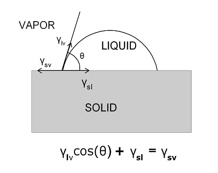
Classic definition of the equilibrium contact angle of a drop of liquid on a surface as the balance of three surface tensions.

Fig.(1). Classic definition of the equilibrium contact angle of a drop of liquid on a surface as the balance of three surface tensions.

When a drop of some liquid is placed on a surface it will typically bead up and form a sessile drop as exhibited in Fig.(1). The angle that the edge of the drop makes with the underlying solid is determined by the balance of three surface tensions or surface energies if you prefer. The concept of surface energy has been covered in some detail in the February 2014 issue of this blog so it will not be reviewed here only to point out that surface tensions as measured in Nt/m are dimensionally the same as surface energies (J/m2) which are readily derived from surface tensions by multiplying the numerator and denominator of the units by m (meter) giving Nt-m/m2 or J(joules)/m2.

And now to our book review:

Wetting of Real Surfaces, By Edward Yu. Bormashenko, (Walter de Gruyter GmbH, Berlin/Boston, 2013)

In this rather compact monograph Prof. Bormashenko provides a rather comprehensive account of the theoretical developments in the field of contact angle and wettability of surfaces.

Interestingly, Prof. Bormashenko points out that the field of contact angle and wettability remained rather a backwater endeavor in the field of modern physics from the time of Thomas Young’s pioneering work up to roughly the 1990’s despite the fact that scientific heavyweights such as Einstein, Schrödinger and Bohr devoted a significant portion of their research activity to this topic. Much of this stems from the fact that surfaces presented a rather messy and intractable research topic due to the difficulty in obtaining well defined surfaces free of contamination and other defects. Indeed the eminent theoretical physicist Wolfgang Pauli remarked that “God created matter but the Devil created surfaces”. Thus the solid state physics literature up to about the early 1980’s tended to be dominated by topics such as superconductivity, electronic band structure, phase transitions, semiconductors and similar topics dealing primarily with the bulk behavior of solids.

This all started to change significantly by about the 1980’s being led in large part by the microelectronics industry which was fabricating multilevel thin film structures which were becoming more and more dominated by interfacial surfaces between metals, insulators and semiconductors.  Even by the early 1970’s it was becoming apparent that in order to fabricate devices with higher and higher circuit densities it was critical to understand the nature of the interactions between the various material components at their contact surfaces. This need was supported by advances in microscopy starting with electron microscopy and evolving further to electron tunneling microscopy and finally to the now ubiquitous atomic force microscopy. On top of this a number of surface analysis techniques emerged nearly too numerous to mention the most popular of which being X-ray Photoelectron Spectroscopy (XPS also called ESCA Electron Spectroscopy for Chemical Analysis).

The need for understanding surface properties was of course not limited to the microelectronics industry. The entire coatings industry needed to understand the wetting properties of various paints and inks and the biotechnology industry dealing with medical implants needed to understand how the surfaces of their devices would interact in the in vivo environment. The contact angle technique thus started to emerge as a low cost and highly sensitive method for exploring the wetting behavior of surfaces.

A critical juncture of sorts was achieved with the work of Barthlott and Neinhuis in 1997[1] who first studied the extreme hydrophobicity of the lotus leaf and its effect in removing all manner detritus from the leaf’s surface. This work lead to a literal explosion of work on the superhydrophobic effect and a variety of applications to self cleaning surfaces and other highly innovative technologies.

Getting back to Prof. Bormashenko’s volume a brief look at the table of contents reveals a rather wide range of topics:

  1. What is surface tension
  2. Wetting of ideal surfaces
  3. Contact angle hysteresis
  4. Dynamics of wetting
  5. Wetting of rough and chemically heterogeneous surfaces: the Wenzel and Cassie models
  6. Superhydrophobicity, superhydrophilicity and the rose petal effect
  7. Wetting transitions on rough surfaces
  8. Electrowetting and wetting in the presence of external fields
  9. Nonstick droplets

There is clearly not enough space here to cover all of the above topics in any detail so we will focus on chapter 6 dealing with super hydrophobic and hydrophilic phenomena which, as Prof. Bormashenko points out, are among the currently most actively researched topics in the contact angle field.

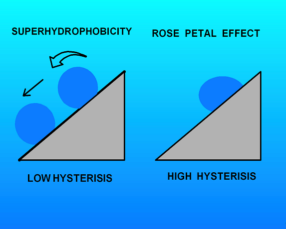
Schematic illustrating the difference between a truly superhydrophobic surface and one exhibiting only a high contact angle

Fig.(2). Schematic illustrating the difference between a truly superhydrophobic surface and one exhibiting only a high contact angle

Interestingly, the author points out that exhibiting a high contact angle is not sufficient to define a state of superhydrophobicity as might casually be assumed. In addition the contacting water drop must also exhibit low contact angle hysterisis.  That is the advancing and receding contact angles must be approximately the same. This property is required for the so called “lotus leaf” effect where water drops not only form with a high contact angle but also roll very easily off the leaf carrying any collected debris with them as shown in Fig.(2).

The counter example is the “rose petal” effect reported on by Jiang and co-workers.[2]  These investigators looked at water droplets on rose petals which also form very high contact angles but unlike the lotus leaf case these drops also exhibit a very strong hysterisis. An immediate consequence is that these drops do not roll even when held at a steep angle as also shown in Fig.(2).

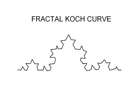
Example of a hierarchical relief morphology.

Fig.(3). Example of a hierarchical relief morphology.

 A further subtle point brought out in the chapter is the fact that the substrate material does not have to be highly hydrophobic in order to exhibit the superhydrophobic effect. The lotus leaf material is in fact hydrophilic. What gives rise to the superhydrophobic behavior is the hierarchical relief morphology of the surface. An example of such a structure would be the fractal Koch curve shown schematically in Fig.(3). The author goes on to analyze the wetting of these highly variegated surfaces in terms of the Wenzel and Cassie models covered in chapter 5.

In all this volume can be highly recommended to anyone interested in coming up to date on the latest theoretical developments in the rapidly expanding field of contact angle phenomena.

The author invites any inquiries or comments on this article.


 [1] “Purity of the Sacred Lotus or Escape from Contamination in Biological Surfaces”, W. Barthlott and C. Neinhuis, Planta, 202, 1 (1997).<
[2] “Petal effect: A superhydrophobic state with high adhesive force”, L. Feng, Y. Zhang, J. Xi, Y. Zhu, N. Wang, F. Xia and L. Jiang, Langmuir, 24, 4114 (2008).
Recommend
3. April 2014   12:39 pm
Dr. K. L. Mittal, Dr. Robert H. Lacombe

Dr. K. L. Mittal, Dr. Robert H. Lacombe

Is Nylon Hydrophobic, Hydrophilic or Maybe Both?

In a recent posting on LINKEDIN Scott Sabreen Owner-President, The Sabreen Group Inc. Initiated the following discussion:


Nylons are inherently difficult to bond because they are hydrophobic, chemically inert and possess poor surface wetting. …

Nylons are hygroscopic and will absorb moisture in excess of 3 percent of its mass of water from the atmosphere. Moisture, in and of itself, creates adhesion problems.  …


Hold on, on the face of it the above remarks would seem to be mutually contradictory.  Is nylon hydophobic or hydrophilic?

The resolution of this apparent paradox comes in recognizing that the hydrophobic behavior of nylon is a surface property and the hydrophilic behavior is a bulk property.

Since nylon is an organic polymer it has a relatively low surface energy as do most polymers.  This is a consequence of the surface chemistry and surface physics of polymers and other organics as discussed in the previous edition of this blog.

However the amide groups in the nylon chain attract water and they give rise to the hydrophilic behavior of this material in regard to BULK ABSORPTION of water.  A number of other polymers such as the polyimides also behave in a similar manner.

So in the bulk nylon can behave as a hydrophilic material but on the surface it can exhibit hydrophobic behavior. Just another hidden property of surfaces that make them both tricky and fascinating to study.

The author invites any inquiries or comments.

Recommend
3. March 2014   12:35 pm
Dr. K. L. Mittal, Dr. Robert H. Lacombe

Dr. K. L. Mittal, Dr. Robert H. Lacombe

Origin of Surface Energy

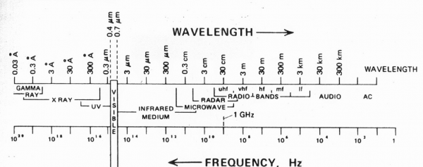
In the December 2013 issue of this blog we noted that nearly all the information we commonly acquire about any given surface comes from the radiation reflected from it.  We also noted that of the entire range of the electromagnetic spectrum available that a surface could possibly radiate, we detect only the so called visible spectrum which amounts to barely 2% of what could be emitted. Thus what our eyes alone tell us about what is happening on a given surface is very limited indeed.  Not only that but the type of information is limited to basically the bulk geometry, gross surface morphology and color.

The fact of the matter is that an entire universe of important physical properties remain invisible to our eyes.  The invisible  property we want to explore here in fact cannot be seen even in principle.  This property is what is called the surface energy and to get a picture of it we need the apparatus of thermodynamics.

The whole concept of energy is rather subtle and intricate in general.  In particular it can take many forms including:

  • Electromagnetic energy stored in electric fields
  • Magnetic energy stored in magnetic fields
  • Thermal energy stored in any material at a finite temperature
  • Potential energy of any mass in a gravitational field
  • Kinetic energy of any moving object
  • Relativistic energy of any massive object as given by Einstein’s famous formula E = mc2
  • etc.

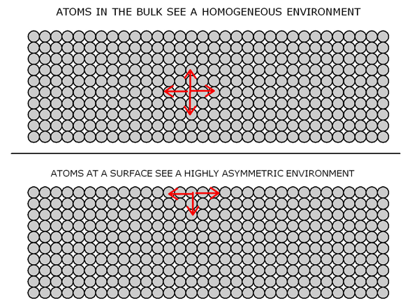
However, for our purposes we only need to understand the elastic energy stored in common solids and we can approach this by considering the behavior of a common spring.  Stretch or compress a spring and it will store a certain amount of elastic energy which can be perceived by allowing the spring to return to its equilibrium length. Much the same type of behavior goes on in common solids.  Figure (1) gives a highly idealized but reasonably realistic picture of a solid material viewed at the atomic level.

Schematic diagram of a solid viewed at the atomic level

Fig. 1: Schematic diagram of a solid viewed at the atomic level. To a first approximation the atoms can be thought of as being held together by microscopic springs which account for the elastic properties of the material.

The atoms/molecules in a given solid are held together by atomic and intermolecular forces which arise from the rather complex electromagnetic interactions among the electrons and nuclei which make up the bulk of any material. Fortunately, near equilibrium and for small deformations these interactions behave in a linear fashion very much like the behavior of simple springs.  Thus as Robert Hook pointed out more than a century ago the restoring force tending to bind the atoms together increases in a linear fashion as they tend to separate from one another. Things get quite a bit more complicated at large deformations but that need not concern us here.

Referring to the upper diagram in figure (1) we see that a typical atom in the bulk of our hypothetical solid feels either tensile or compressive loads from all directions and much the same is experienced by all the rest of the atoms in the deep interior of the solid.  However, the situation is quite a bit different for those atoms at or near the surface as shown in the bottom diagram of figure (1).  Looking down into the bulk of the material they see that same forces as the bulk atoms do but now there is no material on top which creates a highly asymmetrical situation.  It is precisely this asymmetry that gives rise to the unique surface tension or surface energy of the solid.


A Word on Units

Perhaps one of the most confusing things about surface energies are the units they are expressed in so we take a quick break here to clear up this issue.  Going back to our spring, if we stretch it there arises an immediate force tending to return it to the un stretched length.  Current international convention expresses this force in the standard SI units[1] of newtons. All systems of units are essentially arbitrary but it is nonetheless important to settle on a common standard.  Thus the common SI units for force are the newton with the dyne and the pound also in use but not considered standard by the international community.  The newton is the canonical unit of the international scientific community and the dyne is a scaled down derivative.  The pound is an archaic holdover from the past but is still much in use in commercial transactions especially in the USA.

Focusing on the newton it is formally defined as the force required to accelerate a one kilogram weight resting on a friction free surface one meter per second per second.  That means that the weight increases its speed by one meter per second every second under the action of the applied 1 newton load.  We can also thing of the newton in more intuitive if less rigorous terms as the weight of a common apple at sea level.  Thus if you hold a standard sized apple it imparts a force of close to one newton on your hand.  In terms of pounds the apple weighs slightly more that 1/5 th of a pound and in dynes it weighs about 100,000 dynes.

With the concept of force now rigorously defined we move on to the concept of energy again using our standard apple as a prop. Force times distance is energy in the form or work. Let’s assume that the apple weighs exactly 1 newton.  If we raise the apple from the ground to a height of 1 meter we will have done 1 joules worth of work or putting it a little differently we will have increased the apple’s gravitational energy by one joule.

Getting back to our spring, it stores what is called elastic energy.  As stated above energy is force times distance and the restoring force of a spring is proportional to the extension so the energy stored in an extended spring is proportional to force times distance squared.  These ideas can all be compactly summarized in the following formulas:

F = -k x (Restoring force exerted by a stretched spring) (1)

Where:
F = Force in newtons
x = Displacement in meters
k = Spring constant in newtons/meter

The minus sign in Eq(1) indicates the force is always a restoring force tending to oppose any extension or compression.

The energy stored in the spring is the integral of Eq(1) from 0 to some extension d:

W = IFxdx = -(½)kd2 (Energy stored in stretched spring) (2)

Thus if our spring has a spring constant of 1 newton/meter and we extend it to a distance of 1 meter it will pull back with a force of 1 newton.  Also it will store an energy of ½ joule.

We can think of the spring as having a tension of 1 newton/meter which is just another name for the spring constant.  Turning now to the physical surface of a polymer such as nylon the springs binding the atomic units together would have a tension of about 8×10-25 newtons/meter and this is the basis of the so called surface tension or surface energy of this material.  Now in practice we do not deal with such impossibly small numbers so we need to scale things up a bit.  In the case of our nylon, one square meter of the surface will contain something like 5×10²² molecular bonds among the surface moieties or in terms of our simple spring model 5×10²² springs.  So we take the surface tension of our polymer to be the tension in a single bond times the total number of bonds in a square meter which for our nylon material comes to 40×10-3 newtons/meter.  This is still to awkward so we introduce the milli newton (abbr mN) which is 10-3 newtons so nylon now has a surface tension of 40mN/m (abbreviating the meter as m).  Well why stop here.  We can do a little algebra on the units and say that 40mN/m is the same as 40mN-m/m2 by multiplying numerator and denominator by m.  Now the mN-m we recognize as a mJ or milli joule and so our nylon can be thought of as having a surface tension (aka surface energy) of 40mJ/m2.  And it does not stop here.  Many folks dealing with surface tension measurements would rather not have to deal with the milli prefix and such huge surface areas as a square meter.  It is more convenient to scale down the force unit to dynes (10-5 newtons) and use square centimeters (abbr cm) instead of square meters.  Thus 40mN/m scales down to 40 dynes/cm.


Real Solid Surfaces

Now that we have pinned down suitable units for measuring surface energies we can have a closer look at real material surfaces.  The diagrams in figure 1 give a much better depiction of a liquid surface than they do for a solid.  Liquids have a high mobility and can always adjust their configuration to give a uniform surface of minimum surface tension.  Not so with solids.  The surface configuration of a solid depends sensitively on the thermal-mechanical loading conditions under which it was created.  Was the material cooled rapidly or slowly?  What type of loads if any were active during the cooling process?

More realistic depiction of an actual solid surface

Fig. 2: More realistic depiction of an actual solid surface

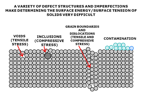
Figure 2 gives a more realistic depiction of what a typical solid surface looks like.  This figure depicts 4 typical surface flaws that can significantly alter the surface energy of any real solid:

  1. VOIDS: Materials that have been rapidly quenched may not have time to completely condense giving rise to voids which are a source of tensile stress that will alter the surface energy in their vicinity.
  2. INCLUSIONS: No material is 100% pure and contamination species have a strong tendency to migrate toward surfaces where they upset the normal packing and in many cases give rise to a local compressive stress.
  3. GRAIN BOUNDARIES/DISLOCATIONS: Nearly all crystalline and semi crystalline materials are polycrystalline in nature.  That is they are made up of an aggregate of a large number of small crystals all packed together in no particular order.  The boundary where two crystallites meet form what is called a grain boundary.  Further the misalignment of planes within the crystalline give rise to what are called dislocations.  These and other imperfections can give rise to local stress fields where they intersect a surface that again alter the local surface energy.
  4. CONTAMINATION: Of all the surface imperfections contamination layers have the profoundest effect on surface energies.  Real material objects sit around on benches in the lab or other platforms where they are subject to constant bombardment from all the contaminants and gases in a typical atmosphere not the mention the greasy fingers of human handlers.

Needless to say all of these considerations make the accurate measurement of the surface energies of solids a rather tricky business. But enough for now.  We take up this question in the next chapter.

The author invites any inquiries or comments.


            [1]The International System of Units (abbreviated SI from French: Le Système international d’unités). A bunch of folks got together and formed the General Conference on Weights and Measures, an organization set up by the Convention of the Metre in 1875, which succeeded in bringing together many international organizations to agree not only the definitions of the SI, but also rules on writing and presenting measurements in a standardized manner around the globe.


Recommend
17. February 2014   8:30 am
Dr. K. L. Mittal, Dr. Robert H. Lacombe

Dr. K. L. Mittal, Dr. Robert H. Lacombe

We interrupt the normal flow of this blog on “SURFACES: THE INVISIBLE UNIVERSE”  to present a book review on a volume which should be of keen interest to all working in the field of atmospheric  plasma technology.  The volume in question is:

ATMOSPHERIC PRESSURE PLASMA TREATMENT OF POLYMERS: RELEVANCE TO ADHESION;  Eds. Michael Thomas and K. L. Mittal (WILEY-Scrivener Publishing, 2013)

The volume contains 15 review articles ranging from surface modification with plasma printing  to the deposition of nanosilica coatings on plasma activated polyethylene.  Each article has been produced by leading experts in the respective topics and gives a truly authoritative examination of the subject matter under review.  A quick look at the table of contents reveals the remarkable scope of this volume.

PART 1: FUNDAMENTAL ASPECTS

  1. Combinatorial Plasma-based Surface Modification by Means of Plasma Printing with Gas-carrying Plasma Stamps at Ambient Pressure;  Alena Hinze, Andrew Marchesseault, Stephanus Büttgenbach, Michael Thomas and Claus-Peter Klages
  2. Treatment of Polymer Surfaces with Surface Dielectric Barrier Discharge Plasmas; Marcel Šimor and Yves Creyghton
  3. Selective Surface Modification of Polymeric Materials by Atmospheric-Pressure Plasmas: Selective Substitution Reactions on Polymer Surfaces by Different Plasmas; Norihiro Inagaki
  4. Permanence of Functional Groups at Polyolefin Surfaces Introduced by Dielectric Barrier Discharge Pretreatment in Presence of Aerosols;  R. Mix, J. F. Friedrich and N. Inagaki
  5. Achieving Nano-scale Surface Structure on Wool Fabric by Atmospheric Pressure Plasma Treatment;  C. W. Kan, W. Y. I Tsoi, C. W. M. Yuen, T. M. Choi and T. B. Tang
  6. Deposition of Nanosilica Coatings on Plasma Activated Polyethylene Films;  D. D.  Pappas, A. A. Bujanda, J. A. Orlicki, J. D. Demaree, J. K. Hirvonen, R. E. Jensen and S. H. McKnight
  7. Atmospheric Plasma Treatment of Polymers for Biomedical Applications;  N. Gomathi, A. K. Chanda and S. Neogi

PART 2: ADHESION ENHANCEMENT

  1. Atmospheric Pressure Plasma Polymerization Surface Treatments by Dielectric Barrier Discharge for Enhanced Polymer-polymer and Metal-polymer Adhesion;  Maryline Moreno-Couranjou, Nicolas D. Boscher, David Duday, Rémy Maurau, Elodie Lecoq and Patrick Choquet
  2. Adhesion Improvement by Nitrogen Functionalization of Polymers Using DBD-based Plasma Sources at Ambient Pressure;  Michael Thomas, Marko Eichler, Kristina Lachmann, Jochen Borris, Alena Hinze and Klaus-Peter Klages
  3. Adhesion Improvement of Polypropylene through Aerosol Assisted Plasma Deposition at Atmospheric Pressure;  Marorie Dubreuil, Erik Bongaers and Dirk Vangeneugden
  4. The Effect of Helium-Air, Helium-Water, Helium-Oxygen and Helium-Nitrogen Atmospheric Pressure Plasmas on the Adhesion Strength of Polyethylene;  Victor Rodriguez-Santiago, Andres A. Bujanda, Kenneth E. Strawhecker and Daphne D. Pappas
  5. Atmospheric Plasma Surface Treatment of Styrene-Butadiene Rubber: Study of Adhesion Ageing Effects;  Cátia A. Carreira, Ricardo M. Silva, Vera V. Pinto, Maria José Ferreira, Fernando Sousa, Fernando Silva and Carlos M. Pereira
  6. Atmospheric Plasma Treatment in Extrusion Coating:  Part 1 Surface Wetting and LDPE Adhesion to Paper;  Mikko Tuominen, J. Lavonen, H. Teisala, M. Stepien and J. Kuusipalo
  7. Atmospheric Plasma Treatment in Extrusion Coating:  Part 2 Surface Modification of LDPE and PP Coated Papers;  Mikko Tuominen, J. Lavonen, J. Lahti and J. Kuusipalo
  8. Achieving Enhanced Fracture Toughness of Adhesively Bonded Cured Composite Joint Systems Using Atmospheric Pressure Plasma Treatments;  Amsarani Ramamoorthy, Joseph Mohan, Greg Byrne, Neal Murphy, Alojz  Ivankoviv and Denis P. Dowling
Schematic two dimensional slice through a typical plasma stamp

Schematic two dimensional slice through a typical plasma stamp

A cursory glance at the above list readily gives one the impression that the applications of the atmospheric plasma technique are limited solely by ones imagination.  It is also clear that this short review will be able to cover only a small fraction of the material covered in this volume.  Quite likely the most innovative paper in the collection is the one on “Combinatorial Plasma-based Surface Modification …” listed as number 1 above.  This work attempts to take the process of plasma surface modification to a higher level through the use of “plasma stamps” which can be used to pattern a substrate with varying levels of plasma treatment in a single run.  A schematic diagram of a plasma stamp is shown in figure (1).  The substrate to be treated is patterned with an array of chambers using poly(dimethylsiloxane) PDMS as an insulator layer.  The resulting array is sandwiched between a porus metal mesh and an electrode.  The metal mesh in this case serves a dual purpose as a gas carrier and as an electrode.

The authors site a number of advantages of the plasma stamp configuration including:

  • Due to the small size of the plasma chambers it is easy to supply nearly unlimited volumes of gas to the active micro-plasmas which is very useful when performing film depositions as opposed to simply performing a surface modification.
  • Again due to the small cavity size the stamp can be rapidly filled using  a small amount of gas.  Thus the process is not only economical in the use of gas but the small chambers can be rapidly purged of unwanted oxygen which is a critical requirement when performing plasma nitrogenation treatments.
  • The small cavity size also allows reaction products created in the cavities that are not deposited to be swept away efficiently in the gas stream.  This is very useful in preventing fouling due to the redeposition of plasma  polymers.
  • Quite likely the most significant advantage of the plasma stamp technology is the fact that quite large arrays  of the plasma micro-cavities  can be created allowing for very efficient combinatorial studies of different  plasma treatments on a single substrate in a single run.  Thus one can easily imagine a 2 dimensional array where two different gas streams are independently introduced to the array from opposite sides of the inlet edge.  The streams will combine continuously across the entire array of cavities giving a well defined gradient of gas composition over the entire array.  Different cavities thereby receive different treatments depending on their location in the overall array.  The results can then be inspected by any of a number of surface analysis methods such as Fourier Transform Infra Red spectroscopy (FTIR) or Xray Photoelectron Spectroscopy (XPS).  Thus a large number of different surface treatments can be screened in a highly efficient manner.

Again the large scope of the volume does not allow us to comment on the other equally interesting articles. It should be clear, however, as mentioned above that the possibilities are limited only by the imagination.

Recommend
27. January 2014   9:33 am
Dr. K. L. Mittal, Dr. Robert H. Lacombe

Dr. K. L. Mittal, Dr. Robert H. Lacombe

This issue of the SURFACE SCIENCE CORNER blog inaugurates a series of essays on the above mentioned topic concerning how we recognize the ubiquitous surfaces we look at all of our waking moments.  The answer of course is through the subtle apparatus of our visual neurology which is activated by the light coming at us from all directions.  The question then becomes what information is all this light carrying to our visual cortex.  However, before we try to unravel this question we need to examine in a little more detail the nature of the light that is being reflected into our eyes from all directions.

Electromagnetic spectrum on a logarithmic scale

Electromagnetic spectrum on a logarithmic scale

The light coming at us is part of what is called the electromagnetic radiation spectrum the entire extent of which is displayed in figure (1).  The striking thing about this figure is the enormous range of the spectrum covering some 20 orders of magnitude on the logarithmic scale shown in the figure.  To print the entire figure on a linear scale would require a sheet of paper extending out to the edge of the solar system assuming 0.1 mm of sheet per 10Hz of frequency.  The second remarkable feature of this diagram for our purposes is the fact that the range of frequencies of visible radiation which is what our eyes detect is less than 2% of the range.  Though we detect a limited number of mechanical and thermal properties of surfaces through direct touch, the preponderance of our awareness of surfaces comes from reflected radiation.  Going by the figure we see that our eyes are missing some 98% of what is potentially being reflected at us.

So what are we missing in particular.  Lets consider first the infrared region from roughly 1011 to 1014 Hz.  This is radiation contributed by the incessant atomic and molecular motions of the atoms and molecules which make up all matter.  To our eyes all surfaces lying at rest are perfectly still certainly at the macroscopic level.  However, consider for example a carbon atom associated with a particular bit of organic contamination residing on some apparently undisturbed surface at room temperature.  An elementary thermodynamic calculation indicates that far from sitting still such an atom is vibrating in place at an average velocity near 300 m/sec.  This motion combined with the motion of all the other atoms and molecules on the surface gives rise to infrared radiation which is beamed in all directions and is entirely invisible to our eyes.  We can, however, detect the molecular vibrations of organic molecules on surfaces with the aid of specialized infrared spectrometers so we know they are there even though we cannot see them.

What else are we missing?  Going to higher frequencies in the range of 1016 to 1019 Hz we find ourselves in the land of the X-rays which reflect information on atomic and molecular structure on the scale of a few angstroms or roughly 10-10 cm.  If we could detect this radiation we would be able to see the atomic and molecular packing of all the species at the surface.  Things like crystal structure, grain boundaries, dislocations and assorted other types of contamination and defects lying on the surface.  In addition we would be able to detect the inherent roughness of the surface at the atomic and molecular scale.  What to the eye would appear to be a perfectly smooth surface when observed with X-rays would appear to be quite rough an rugose.  Such variable surface topography can have quite significant effects on common properties such as surface wettability.

Going to yet higher frequencies we find ourselves in the range of the gamma rays which live in the range from roughly 1019 to 1020 Hz.  The gamma rays allow us to peer into the goings on in the atomic nucleus some 1000 times smaller than the typical atom.  In particular, some nuclei are unstable and can disintegrate into smaller nuclei giving off gamma rays and other particles in the process.  Most common materials are not radioactive but some do have contamination level concentrations of radioactive species which can give off barely detectable amounts of radiation.  Now one might not expect that sub detectable levels of radiation would be of much concern to the practical product engineer manufacturing some wholly macroscopic device for industry.  However, the world of surfaces can be quite subtle and engineers in the microelectronics industry got an elementary lesson in nuclear physics from that most common of common materials lead.  It turns out that lead can harbor contamination levels of radioactive species the activity of which are quite invisible to our eyes as explained above.  Lead has a long history of being used to make electrical connections in the electronics industry going back to at least the mid 19th century.  It so happened that in the early 1980’s lead solder was being used to connect sensitive memory chips to ceramic substrates.  The memory chips were of a special kind which utilized the very high resistivity of single crystal silicon to trap a small amount of charge in a small cell which formed the basis of an elementary unit of memory.  A cell containing charge served as a boolean “1″ and an empty cell represented a boolean “0″.  All well and good but all the cells had to be connected to the remaining computer circuitry using metal lines and interconnects and of course that old work horse lead served as one of the interconnect materials.  The reader can now well guess what happened.  The radioactive contaminant species in the lead would decay from time to time giving off not only a gamma ray but also a highly charged alpha particle.  The alpha particle was the main mischief maker.  Carrying a charge of +2 it does not travel very far in ordinary matter but where it does go it leaves behind a trail of ionization which can momentarily turn a highly resistive material like single crystal silicon into a good conductor along the path of the alpha particle.  One can easily imagine a wayward alpha particle crashing into one of the silicon memory cells causing a charged cell to discharge along the ionization path left by the alpha.  A memory register of the computer has now been randomly and irreversibly changed which is not good from the point of view of programming logic.  If the affected register happened to contain an important logic instruction the result would easily lead to a serious programming error or simply machine lockup.  The field engineers came to know this type of problem as a “soft” error since the ionization trail left by the alpha particle would quickly dissipate leaving the affected memory cell quite unharmed.  Thus any attempt to locate the source of the error would be futile since no permanent hardware malfunction was involved.  Such so called “soft” errors are the worst kind from the point of view of the field engineer.  They come at random from seemingly nowhere and the culprit escapes without a trace.  How this problem was eventually solved is a story for another time but for now it simply illustrates that what we cannot see coming off a surface can indeed bite us in wholly unsuspected ways.

If we now go to the lower frequencies from 104 to 1011 Hz we come across the radio and microwave bands.  If we could detect these frequencies we would be able to see the myriad electronic and polarization currents which endlessly flow in all materials and give rise to a number of phenomena which affect us in various ways even though we cannot visually see them.

All this will be covered in future issues of the SURFACE SCIENCE CORNER blog.

The author invites any inquiries or comments.

Recommend